Electrical Single Line Diagram : Single Line Diagram of Power System ~ your electrical home : The illustrated block diagram is of the electrical system only.
Electrical Single Line Diagram : Single Line Diagram of Power System ~ your electrical home : The illustrated block diagram is of the electrical system only.. In this post you'll learn what is single line diagram and why do we need it. In the single line diagram, the system component is usually drawn in the form of their symbols. When used with text material, it gives you a basic understanding of the functions of the components of a system. Savesave electrical single line diagram for later. It uses single lines and graphic symbols.
The purpose of single line diagram is to diagrammatically show sources of power, electrical equipment loads, electrical drives, system details and fault levels. Single line diagram or one line diagram is the fundamental modelling of power system that is required in every power system analyze. Understanding fault characteristics of a typical electrical power system is shown in figure 2. Our electrical power systems primarily contain three phases of ac circuits. Often the diagram is simplified further by omitting the neutral wire and by indicating the component parts by standard symbols rather than by their equivalent circuits.
Single Line Electrical Diagram | Hawaiian Electric from www.hawaiianelectric.com Single line diagram of power plant. This enables the user to place two different representations down of the same component. Often the diagram is simplified further by omitting the neutral wire and by indicating the component parts by standard symbols rather than by their equivalent circuits. In the single line diagram, the system component is usually drawn in the form of their symbols. The set of single line diagram form the basics of all electrical work carried out in a project. 100%(2)100% found this document useful (2 votes). It shows a correct power distribution. Also it have ht cables, lt cables & earthing system.
3.1, shows the single line diagram of electrical system of a very simple electrical power system.
Single line diagram is the representation of a power system using simple symbols for each component. Some wiring diagrams are so large and contain so many. The recently added movie on the cadline community entitled producing single line diagrams shows you how. Single line diagram drawing tells the worker at a glance where the disconnecting means is located. This means each transmission or distribution power line appears as a single line on the page, rather. A single line diagram is a roadmap of the main components of your electrical system. The purpose of single line diagram is to diagrammatically show sources of power, electrical equipment loads, electrical drives, system details and fault levels. This enables the user to place two different representations down of the same component. Also it have ht cables, lt cables & earthing system. Savesave electrical single line diagram for later. Please look into providing a tool pallet consisting of typical electrical symbols that are used to develop a single line diagram. It could also be under a different view altogether, exclusive and specific for drawing single line diagrams. In the single line diagram, the system component is usually drawn in the form of their symbols.
Our electrical power systems primarily contain three phases of ac circuits. In the single line diagram, the system component is usually drawn in the form of their symbols. The diagram includes the component devices or parts used in the circuit. It uses single lines and graphic symbols. 3.1, shows the single line diagram of electrical system of a very simple electrical power system.
Single Line Diagram Drawings, Designing Software: Cad ... from 4.imimg.com Also it have ht cables, lt cables & earthing system. Each line is represented by a single line instead of three or four conductors. It includes all redundant and. 100%(2)100% found this document useful (2 votes). The purpose of single line diagram is to show sources of power,electrical. Single line diagram drawing tells the worker at a glance where the disconnecting means is located. The sld shows all pertinent information about the sequence of the circuit,but does not give as much detail as a schematic diagram. It shows a correct power distribution.
Also it have ht cables, lt cables & earthing system.
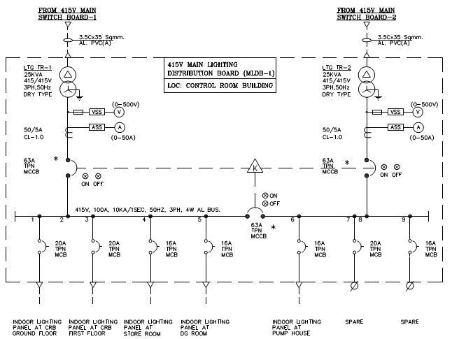
Single line diagram sld gives the information about how the electrical system is distributed through out the plant. When interpreting a single line diagram, you should always start at the top where the highest voltage is and work your way down to the lowest voltage. Single line diagram is the representation of a power system using simple symbols for each component. As a layman view, sld is nothing but consisting of various components of the electrical system like, transformer, dg, panels consisting of ht breaker, lt breaker, ct, pt, fuses, meters, capacitor and many on. Each line is represented by a single line instead of three or four conductors. Electrical elements such as circuit breakers, transformers, capacitors, bus bars, and conductors are shown by standardized schematic symbols.instead of representing each of three phases with a separate line or terminal. The recently added movie on the cadline community entitled producing single line diagrams shows you how. Also it have ht cables, lt cables & earthing system. Some wiring diagrams are so large and contain so many. These illustrate the course of an electric circuit or system of circuits. Savesave electrical single line diagram for later. Multiple generators & grid connections. This enables the user to place two different representations down of the same component.
A single line diagram or sld is a simple visual representation of three phase power systems. It is the first step in preparing a critical response plan, allowing you to become thoroughly familiar with the electrical transmission. The diagram includes the component devices or parts used in the circuit. The set of single line diagram form the basics of all electrical work carried out in a project. Our electrical power systems primarily contain three phases of ac circuits.
Single Line Diagram Services In Kolkata, Single Line ... from cpimg.tistatic.com In the single line diagram, the system component is usually drawn in the form of their symbols. Single line diagram or one line diagram is the fundamental modelling of power system that is required in every power system analyze. Electrical elements such as circuit breakers, transformers, capacitors, bus bars, and conductors are shown by standardized schematic symbols.instead of representing each of three phases with a separate line or terminal. A single line diagram is a roadmap of the main components of your electrical system. 100%(2)100% found this document useful (2 votes). The illustrated block diagram is of the electrical system only. Understanding fault characteristics of a typical electrical power system is shown in figure 2. The station transformer derive power from ehv buses and deliver to the station buses buses 3 to 6.
It shows how all alternate sources may be isolated.
The station transformer derive power from ehv buses and deliver to the station buses buses 3 to 6. It could also be under a different view altogether, exclusive and specific for drawing single line diagrams. Also it have ht cables, lt cables & earthing system. Understanding fault characteristics of a typical electrical power system is shown in figure 2. Single line diagram sld gives the information about how the electrical system is distributed through out the plant. Electrical elements such as circuit breakers, transformers, capacitors, bus bars, and conductors are shown by standardized schematic symbols.instead of representing each of three phases with a separate line or terminal. The set of single line diagram form the basics of all electrical work carried out in a project. Please look into providing a tool pallet consisting of typical electrical symbols that are used to develop a single line diagram. It shows how all alternate sources may be isolated. Single line diagram or one line diagram is the fundamental modelling of power system that is required in every power system analyze. These illustrate the course of an electric circuit or system of circuits. Some wiring diagrams are so large and contain so many. These types were as follows:
You have just read the article entitled Electrical Single Line Diagram : Single Line Diagram of Power System ~ your electrical home : The illustrated block diagram is of the electrical system only.. You can also bookmark this page with the URL : https://targimnh.blogspot.com/2021/06/electrical-single-line-diagram-single.html
Share Awesome
Belum ada Komentar untuk "Electrical Single Line Diagram : Single Line Diagram of Power System ~ your electrical home : The illustrated block diagram is of the electrical system only."

Belum ada Komentar untuk "Electrical Single Line Diagram : Single Line Diagram of Power System ~ your electrical home : The illustrated block diagram is of the electrical system only."
Posting Komentar